Accession No
3415
Brief Description
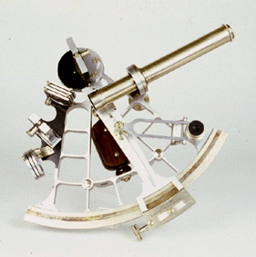
sextant, by James Joseph Hicks, English, 1893
Origin
England; London; Hatton Garden; 8-10
Maker
Hicks, J.
Class
navigation
Earliest Date
1893
Latest Date
1893
Inscription Date
Material
metal (aluminium, silver, other (nickel?)); wood; glass; cloth (baize)
Dimensions
box breadth 286mm; depth 257mm; height 121mm
Special Collection
Provenance
Transferred from Institute of Astronomy, University of Cambridge, Cambridge, England, 1986.
Inscription
‘J. HICKS. MAKER
8.9&10. HATTON GARDEN LONDON’
‘J. HICKS
8, 9 & 10, Hatton Garden
LONDON.’ (on plaque on lid)
Description Notes
Sextant, by James Joseph Hicks, English, 1893.
Aluminium framed sextant, unusual framework made up of square compartments, with 2 pins connecting to the wooden handle below. 4 shades for the index mirror. 3 shades for the half-silvered horizon glass. Detachable eyepiece. (Two screw-fit eyepieces, one with parallel wires. Two eyepiece shades; 8-2-2000).Telescopic mount adjusted by knurled screw. Pocket magnifying glass. Silver scale divided [-5]-[150] by 10 to 20 minutes (to 10 minutes; 8-2-2000), read by vernier to 10 seconds of arc. Index arm with reading glass on subsidiary arm. Screw and clamp. Laquered wood handle bar. Three feet.
Fitted wooden box lined with green baize.
Certificate of Examination pasted inside lid of box from the Kew Observatory, Richmond, Surrey; dated 2-1893.
Condition: good; complete (?; spaces for other parts in box; 8-2-2000).
References
Events
Description
Today navigation instruments such as radar, radio and satellites update a ship’s position continuously. During the 17th and 18th centuries manual calculations had to be made using instruments such as the backstaff, octant or sextant.
The term “sextant” refers to an arc of 60°. The sextant is a portable instrument that measures angles between distant objects. It is an instrument that has been used in the fields of astronomy, surveying and navigation. When navigating, the sextant is used to measure latitude to an accuracy of 0.01 of a degree. To use the sextant the navigator moves the index arm until the index mirror appears to line up the sun within the horizon mirror. By reading the angle off the index arm, the angle of the sun (and therefore the ship's latitude) can be calculated.
Much thought was put into the design for the sextant in an attempt to make them as accurate as possible. The first examples of sextants were made of brass and were mostly large and heavy. Over time the frame was designed to be rigid and light. A successful and popular design in the 18th Century was the “double-frame” or “pillar frame” sextant which was patented by Troughton in 1788. An example of this sextant can be seen in the navigation case.
The Search for Longitude
The sextant was also used in an attempt to determine longitude as well as latitude. In the 1750’s Tobias Mayer’s design of a reflecting circle was given to the British Board of Longitude who gave the instrument to Captain John Campbell to test fully at sea. Campbell liked the idea but found the circle too awkward to use. John Bird was ordered by Campbell to design a 60° arc (the sextant), which he thought to be adequate for the longitude measurements required. (To discover more about the search for longitude have a look at some of the books).
FM:43045
Images (Click to view full size):