Accession No
6152
Brief Description
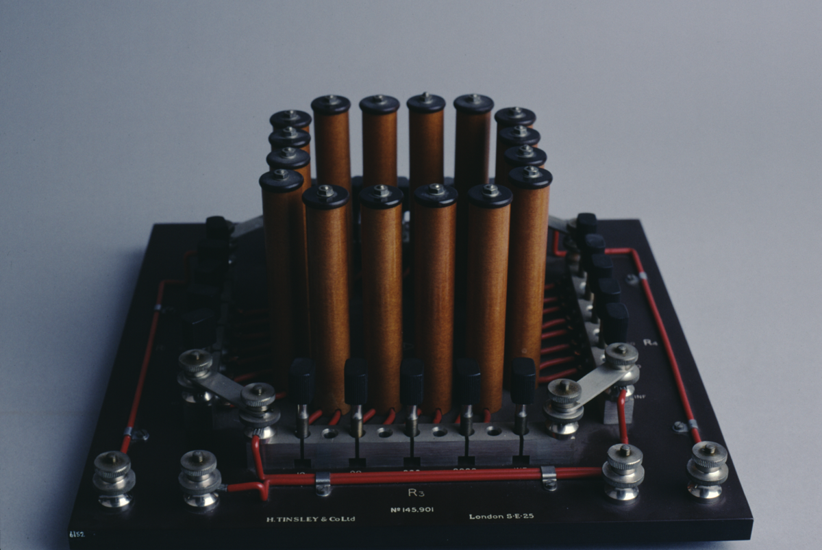
students A.C. bridge network, by H. Tinsley and Company Ltd., English, mid-20th Century
Origin
England; London S.E.25
Maker
H. Tinsley and Company Ltd.
Class
electrical; demonstration
Earliest Date
1920
Latest Date
1970
Inscription Date
Material
plastic (Bakelite; other (pvc?)); metal (stainless steel)
Dimensions
length 305mm; width 305mm; height 140mm
Special Collection
Provenance
Donated on or before 23/01/2003. The donor collected the instruments over many years, predominantly from private sales, some were obtained direct from the manufacturers who were going to throw them out.
Inscription
“STUDENTS A.C. BRIDGE NETWORK”
“TYPE 3437”
“No. 145,901”
“H. TINSLEY & Co. Ltd. London S.E.25”
Description Notes
Students A.C. Bridge Network, by H. Tinsley & Co. Ltd., mid twentieth century.
Bakelite square base with four equal ratio arms mounted on top. Each arm having resistors of value 10, 90, 900, 9000 ohms and infinity. These resistors are connected via wires to seperated stainless steel blocks that can be connected together (thus bipassing the resistor it is attached to) using movable steel pegs that fit into holes that lie between the blocks. If not required to connect adjacent blocks, these pegs can be stored in holes set into the middle of the blocks.
Each ratio arm is connected to the next via a stainless steel bridge, held between two steel screws. This bridge can be removed if required. Ratio arms are also connected to seperate screw attachments via wires (sheathed in red plastic). These seperate attachments can be used to connect the object to accessories, such as resistance boxes or capacitors.
References
Events
Description
Designed to enable the construction of electrical bridges by students, who could then manipulate them using the movable pegs to alter the path of the circuit through the resistors in the four ratio arms. This enabled the teaching of the principles of A.C. Bridges, including the measurement of inductance, capacitance and resistance, depending on what type of accessories were attached to the object.
The bridge would usually be powered by a 6V secondary of a small tranformer, and common bridges for standardized measurement -- such as the Wheatstone Bridge for the measurement of resistance -- could then be constructed and manipulated by the student.
07/08/2007
Created by: Joshua Nall on 07/08/2007
FM:46617
Images (Click to view full size):