Accession No
6170
Brief Description
lineman’s test set, by unknown maker, although possibly produced by Ferranti, as the ammeter used in the device is by Ferranti, early to mid-20th Century
Origin
Maker
Ferranti [tentative attribution]
Class
electrical; engineering
Earliest Date
1920
Latest Date
1940
Inscription Date
1940
Material
wood (teak); metal (stainless steel; brass); plastic; glass; leather
Dimensions
height 203mm; width 195 mm; depth 150mm
Special Collection
Provenance
Donated on or before 23/01/2003. The donor collected the instruments over many years, predominantly from private sales, some were obtained direct from the manufacturers who were going to throw them out.
Inscription
TEST SET PORTABLE No 2
Diagram No. 1198
[numerous inscriptions on brass plate inside lid, detailing how to do “LINE TESTING” and “TO TEST SINGLE CELLS”]
[numerous inscriptions on brass plate on front of box, in table format, denoting resistance reading by comparison of “TEST DEFLECTION” against “CALIBRATING DEFLECTION”
Description Notes
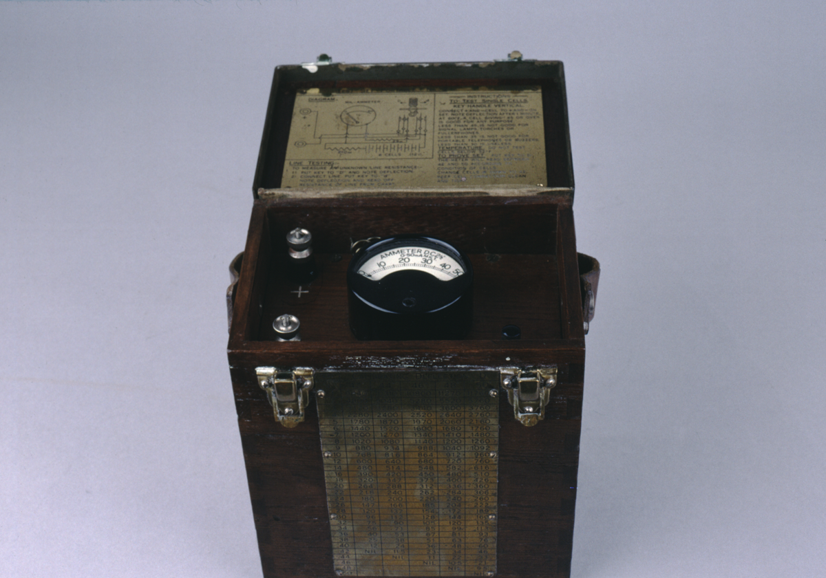
wooden box with hinged lid, plus leather carrying strap. edges of lid plus edges of rear surface of box are edged in brass; hinges are brass.
On front of box is a brass plate, inscribed with a data table of resistance values, which can be read off against a “CALIBRATION DEFLECTION “D”” (split into 5 columns, 42; 44; 46; 48; and 50) versus a “TEST DEFLECTION “d”” (50 rows, from 1 to 50).
Lid is held shut by two brass clips. On inside of lid is another brass plate, this one inscribed with a diagram of a correctly set up circuit for the apparatus, plus instructions for “LINE TESTING” and “TO TEST SINGLE CELLS” and “TO PROVE SET”
set inside the box is a wooden surface which contains a Ferranti moving coil Ammeter (D.C. 2 1/2”, 0-50 mA, M.K.1) dated 1940. The ammeter is circular, with a black plastic body and a semicircular glass window, showing a gradiated scale marked 0-50. Also on the wooden surface is two stainless steel screw fittings for wires (marked “+” and “-”), and one switch (with black plastic handle) that can be moved between “D” and “d”
Below the wooden surface is a space for holding the test set’s cells (not extant in this object), which can be accessed by removing the brass edging around the back surface of the box.
References
Events
Description
Lineman’s test sets were used by telephone or telegraph engineers to find the resistance of a line.
The test set would contain a series of battery cells - from these a calibration reading would be taken by the engineer (this was necessary to do each time because the calibration reading would vary depending on the temperature of the battery cells). The engineer would then attach the test set to the line he was testing and make a test reading. By reading off the test reading against the calibration reading on the table etched into the brass plate on the front of the box, the lines resistance could be found.
The test set could also be used to check the current output of individual cells used to drive signal lamps, torches, fullerphones, portable telephones or buzzers.
06/09/2007
Created by: Joshua Nall on 06/09/2007
FM:46636
Images (Click to view full size):