Accession No
2189
Brief Description
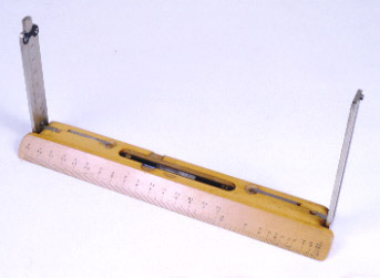
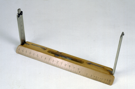
Plane table alidades by Secretan, early 20th C. One with a sturdy canvas case.
Origin
Paris; France
Maker
Secretan
Class
surveying
Earliest Date
1900
Latest Date
1930
Inscription Date
Material
metal (brass, oxidized brass and white metal); glass; wood (boxwood); cloth (canvas)
Dimensions
overall length 234mm; height 106mm
Special Collection
Provenance
Transferred from Department of Geography, University of Cambridge, Cambridge, England, 05/1969.
Inscription
‘SECRETAN
A PARIS’ (on front)
‘INSTRUCTION SUR L’ALIDADE NIVELATRICE’ (on reverse)
Description Notes
2189a: Boxwood alidade with metal alloy window and pinhole sights. Graduated either side of window 0 - 40 (right), 70 - 30 and 35 - 0 - 5 (left) numbered by 5 subdivided to 1. Sliding pinhole bar graduated 40 - 75 numbered by 5 subdivided to 1. Bubble level mounted in base. Levers either end to raise and lower the base. Edge of base graduated 0 - 15 cm in both directions numbered by 1 divided to 1 mm, also divided 0 - 100 on a rapidly diminishing scale. Canvas case.
Condition good; complete
2189b: Boxwood alidade with metal alloy window and pinhole sights. Graduated either side of window 0 - 40 (right), 70 - 30 and 35 - 0 - 5 (left) numbered by 5 subdivided to 1. Sliding pinhole bar graduated 40 - 75 numbered by 5 subdivided to 1. Bubble level mounted in base. Levers either end to raise and lower the base. Edge of base graduated 0 - 15 cm in both directions numbered by 1 divided to 1 mm, also divded 0 - 100 on a rapidly diminishing scale.
References
Events
Description
Plane table alidade
A plane table is a flat square board, with a piece of paper attached to the top surface on top of which an alidade (sighting rule) is secured. The apparatus also requires a magnetic compass for orientation.
This allows for one of the most direct and convenient methods of surveying. Initially, a point is drawn to represent the first surveying station. Lines of sight to certain objects can then be taken with the alidade are marked on the paper using the rule. The table is then moved to the second location and oriented in the same way using the compass. The distance moved is represented on the paper by an appropriate scale. The same lines of sight are then taken again and the intersects of the two sight lines show where the object is. This process allows a plan of the site to be created.
18/10/2002
Created by: Saffron Clackson on 18/10/2002
FM:39609
Images (Click to view full size):